Perspective-correct interpolation
Projection only moved the positions. Everything else the vertex carries (UV, normal, color) got left behind. If you project something, every piece of data it carries has to be projected too. This card is about going back for the pieces we skipped.
What goes wrong
clip /= clip.w pushes the three vertex positions onto the screen. The UV, normal, and color attached to each vertex never go through that divide. They’re still sitting in 3D.
GetBarycentricWeights measures proportions on the screen. Using screen proportions to mix data that’s still in 3D mixes two different spaces, and the answer comes out wrong.
How wrong? Points that are evenly spaced in 3D are not evenly spaced once projected. The far ones bunch up. Halfway across the triangle on screen might only be 20% of the way across the real triangle.
The fix: three steps
- Divide each vertex’s attribute by that vertex’s depth. Now the attribute has been “projected” too.
- Interpolate normally with the screen weights. Both sides are in the same space now, so this is valid.
- Multiply back by this pixel’s depth, to turn it back into a real attribute value.
Step 3 needs the pixel’s depth, which you also have to interpolate. Same trick: interpolate , then take the reciprocal.
Math
= camera-space depth of each vertex (clip.w). = screen-space barycentric weights.
First line gets the pixel’s depth. Second line is the three steps: divide, interpolate, multiply back.
Why multiplying by doesn’t just cancel the divide
You divide by three vertex depths () and multiply by one pixel depth (). Four different numbers, so nothing cancels.
Expand it and each term picks up a factor . Near vertices (small ) get a bigger factor, far ones get a smaller one. That reweighting is the correction.
The only time they cancel: all three vertices at the same depth (triangle facing the screen head-on). Then every factor is 1 and it’s just normal interpolation. That’s why a flat 2D scene shows no difference.
Segment form
Same idea on a line instead of a triangle. Two endpoints, one parameter instead of three weights.
On a segment, a point’s weight comes from the length of the piece opposite each endpoint. On a triangle, from the area of the piece opposite each vertex. Most explanations online use the segment version; the slides use the triangle version.
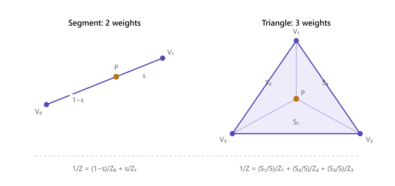
Two different z’s
Easy to mix up. They describe the same depth on two different scales.
| What it is | Use it for | |
|---|---|---|
ndc.z | Already divided by w, squeezed into [0,1] by the projection matrix | Depth test. Interpolates fine as-is. |
clip.w | Real distance from the camera | The formula above. ndc.z can’t replace it. |
Code
// vertex stage: clip.w is the real depth, and dividing destroys it
glm::vec4 clip = viewProj * worldPos;
camZ[i] = clip.w;          // save it first
clip /= clip.w;

// fragment stage
glm::vec3 bary = GetBarycentricWeights(pos2D, pixel);
float z = 1.f / (bary.x/camZ[0] + bary.y/camZ[1] + bary.z/camZ[2]);
glm::vec2 uv = z * (bary.x*uv0/camZ[0] + bary.y*uv1/camZ[1] + bary.z*uv2/camZ[2]);
Normal and color use the same line as uv. Compute z once, reuse it.
Gotchas
- Save
clip.wbefore dividing. Afterclip /= clip.wit’s 1 and the real depth is gone. - Barycentric weights must use 2D screen area, not 3D surface area. Keep the weight function 2D.
- Normalize the normal after interpolating. Mixing three unit vectors gives something shorter than 1.
- A 2D scene proves nothing. All depths equal means the correction does nothing. Test on a tilted 3D surface.
- Skipping this entirely gives the warped, swimming textures of PS1 games.
- On a GPU this happens automatically. A GLSL
in vec2 uvarrives already corrected.
One line to remember
Geometry uses the divided values. Attributes need the depth from before the divide.
Related
Coordinate spaces (rendering pipeline)
Barycentric interpolation
Rasterization
UV mapping
Texture sampling
Depth testing (Z-buffer)
Lighting